Application/W.P. : Generally for outer & indore use, For armoured & unarmoured Cables.
FLP : Generally used In flammable Gas I Vapour, area suitable
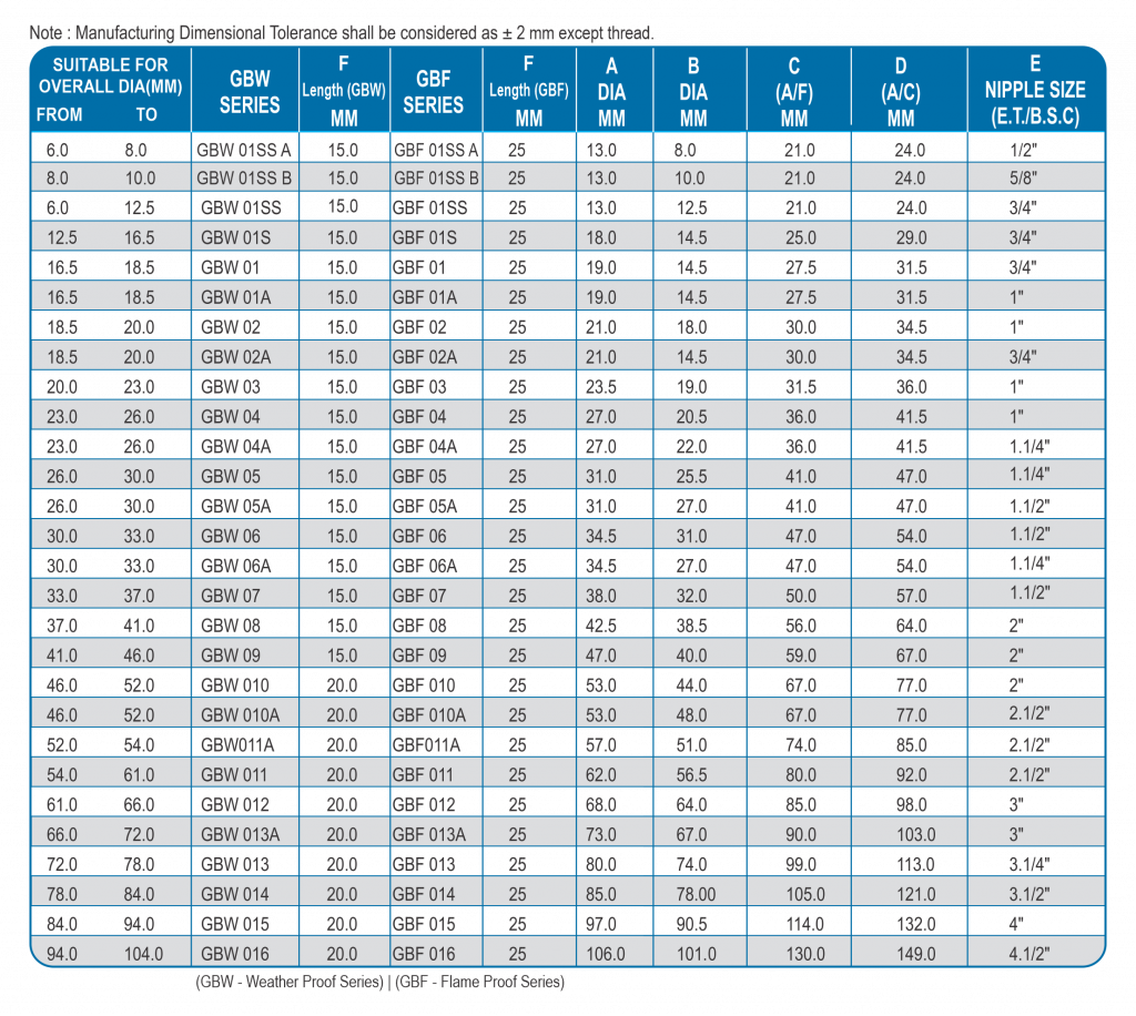
SERIES : for Gas Group I, llA & llB GBW / GBF
Application
Weather Proof Glands are used in Regular Climatic Conditions, Which are Water Proof & Dust Proof (IP 67). With the Protection of PVC Hood itcan be used in Different Areas.
Flame Proof Glands are generally used in hazardous area, as well as in normal climatic conditions also, which are also weather proof, water proof & dust proof (IP 66). with the protection of PVC Hood itcan be used in different areas.
Certification
GLANDS are approved by CSIR CIMFR Testing cell, Dhanbad. Test Certificate No. CIMFR/TC/P/762 for Weather Proof Double Compression Cable Glands
Test certificate No. CIMFR/TC/P/763 and test & assessment report No. IN/CIMFR/TR19/H-206 for flame proof Double Compression Cable Glands Glands are also approved by BIS, CE & ROHS.
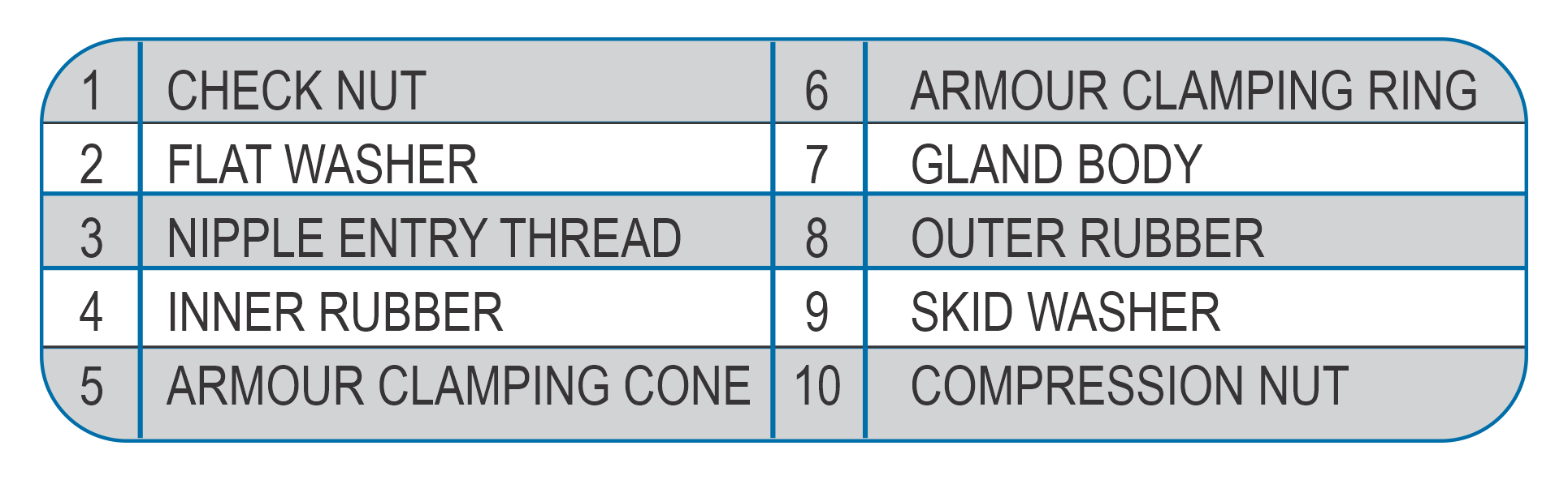
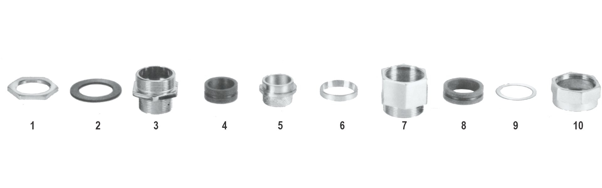
Parts of Glands :
1) Check Nut, 2) Washer 3) Nipple Entry Thread,
4) Inner Rubber 5) Armour Clamping Cone,
6) Armour Clamping Ring, 7) Main Gland Body,
8) Outer RUbber, 9) Skid Washer, 10) Compression Nut. All the metal parts are made of brass,
as per the Approved Drawing.
Fitting Sequence
Insert Part 10, 9, 8 & 7 respectively_ on the Outer Sheath of the cable before exposing the armour,
After removing over sheath of the cable, insert part 6 over the exposed armour,
Size armour length, lift armour, & insert part 5 under the armour, taper part facing inward side, squeeze part No. 5, by pushing part No.6, towards it
Insert Part 4 & 3 on inner sheath, then tight part No. 3 with Part No. 7 , & tight part No.10 with part No. 7
Finally apply the full fitted gland in the enclosure with the entry thread provided, if The enclosure does not have thread then tight the gland with the part No.1 provided.
Accessories :
PVC Hood, Earth Tag, Stopping Plug, Reducers, Adaptors, etc are available with specified dimensions, in accordance to the gland separately.